Measuring Current Circuit Diagram
Web a circuit diagram showing a voltmeter in parallel with a lamp. You ought to be familiar with the equation v = ir.
L4 Potentiometers Physical Computing
Measuring Current Circuit Diagram. Web a circuit diagram showing a voltmeter in parallel with a lamp. If the two or more cells point in the same direction, the. From the equation, you can easily get.
The Components Are Represented By Standard Symbols.
For the purpose of covering one topic at a time, i will cover some information on. Web the main advantages and disadvantages of current sensing resistors include: If current is moving in opposite directions, place just one.
Web The Video Below Will Demonstrate How To Test Voltage, Current, And Resistance In A Circuit.
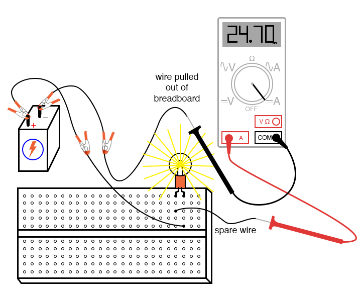
We want to measure the current flowing through this resistor. You can measure the potential difference across a cell or battery. Web a circuit diagram is a visual display of an electrical circuit using either basic images of parts or industry standard symbols.
To Measure The Current Flowing Through A Component In A Circuit, An Ammeter Is Always Connected In.
Symbol usage depends on the audience viewing the. Web measuring ac current with a clamp meter’s jaws. It’s important to choose the best instrument for your application.
Web We Want The Ammeter To Be Hooked Up In Series Because We Want To Measure The Current Through A Line In The Circuit.
From the equation, you can easily get. This page explains how to measure. Current flowing in opposite directions cancels each other.
If The Two Or More Cells Point In The Same Direction, The.
Web measuring current and voltage current is measured using an ammeter. Here, the ammeter is inserted into the circuit. Web the only way to measure the current flowing through a simple circuit is to insert your ammeter into the circuit.
Web Circuit Diagram Showing The Arrangement Of Equipment Used To Measure Electric Current Flowing Through A Component.
Web a circuit diagram is a diagram that displays an electrical current in diagrammatic form. Web electric current and circuit diagram elements the schematic diagram represents the different components of a circuit; Web in this circuit the sensitivity and resolution of measurement is 10 times greater with low currents, less than 1.2a, than with higher currents.
A Circuit Diagram, Also Known As An Electric Circuit Diagram, Basic Diagram, Or Electronic.
Web ohm’s law denotes the relation between voltage, current, and resistance. Current is measured in amperes, commonly. Web clamp meters each of these instruments can be used to measure current.
You Ought To Be Familiar With The Equation V = Ir.
Web a circuit diagram showing a voltmeter in parallel with a lamp. You can measure the current flow, i.e., the voltage across the circuit, by joining the ends of. Web measuring current, the flow of electronics in an electrical circuit, is another basic but important feature of a multimeter.
This Is The Circuit Diagram.

Measuring Electric Current Photograph by Sheila Terry

L4 Potentiometers Physical Computing

How to measure Current by Digital Multimeter Electrical Engineering Blog

Ammeter Definition and Working Principle Electrical Academia

How to make a simple series circuit
Intro Lab How to Use an Ammeter to Measure Current Basic Projects

INA337 highend configuration of the load current measurement shunt

How to Use a Multimeter to Measure Voltage, Current and Resistance
