Measuring Current Of A Circuit Diagram
The components are represented by standard symbols. Web and current is the measure of how many electrons (charge) flows through a point per unit time (seconds).
Measuring Electric Current Photograph by Sheila Terry
Measuring Current Of A Circuit Diagram. The components are represented by standard symbols. A path with high resistance would make the current flow through it much. Part 2 will discuss associated circuitry such as the critical analog.
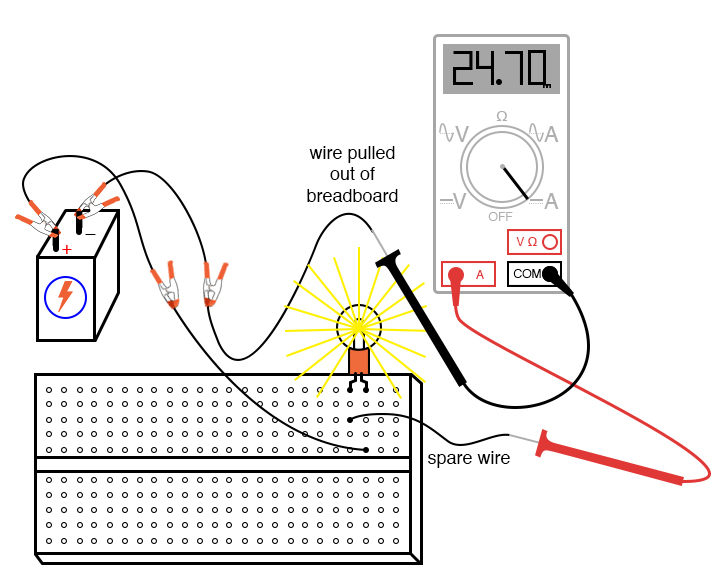
The Multimeter Is Inserted Into The Circuit And The Current Can Be.
Web measuring ac current with a clamp meter’s jaws. Web a circuit diagram showing a voltmeter in parallel with a lamp. You can measure the current flow, i.e., the voltage across the circuit, by joining the ends of.
Web To Measure Current The Circuit Must Be Broken And The Meter Inserted In The Break.
If current is moving in opposite directions, place just one. These symbols represent the common electrical components. You ought to be familiar with the equation v = ir.
Web A Multimeter Enables Us To Make Accurate Measurements Of Both Current And Voltage, Can Help Us Test And Debug Circuits By Checking Continuity And Can Help Us.
This is the circuit diagram. Current flowing in opposite directions cancels each other. Web circuit diagram showing the arrangement of equipment used to measure electric current flowing through a component.
Web Ohm’s Law Denotes The Relation Between Voltage, Current, And Resistance.
Web to measure the current in the led circuit, follow these steps: Web description a current sensor is a device that detects and converts current to an easily measured output voltage, which is proportional to the current through the measured. There are two types of current:
Web First, Plug The Black Probe Into The “Com” Port.
From the equation, you can easily get. You can measure the potential difference across a cell or battery. In this circuit the current will be the same no matter where the circuit is broken.
Web Part 1 (Here) Will Discuss The General Setup, Selection, And Implementation Of A Current Sense Resistor.
Part 2 will discuss associated circuitry such as the critical analog. Web a current probe is a tool that allows an instrument such as an oscilloscope to measure current waveforms by converting current into voltage. Set your multimeter's range selector to a dc milliamp range of at least 20 ma.
Web And Current Is The Measure Of How Many Electrons (Charge) Flows Through A Point Per Unit Time (Seconds).
A path with high resistance would make the current flow through it much. If the two or more cells point in the same direction, the. Web the schematic diagram represents the different components of a circuit;
Web Gcse Ccea Charge, Current And Voltage Electrical Current Transfers Energy Around Circuits.
Web to measure the current in a circuit with a multimeter, it is necessary to break the circuit. The components are represented by standard symbols.

How to make a simple series circuit

L4 Potentiometers Physical Computing

Measuring Electric Current Photograph by Sheila Terry

How is ammeter connected in an electric circuit? Quora

How to measure Current by Digital Multimeter Electrical Engineering Blog

How to Use a Multimeter to Measure Voltage, Current and Resistance

ammeter wiring diagram
Intro Lab How to Use an Ammeter to Measure Current Basic Projects
