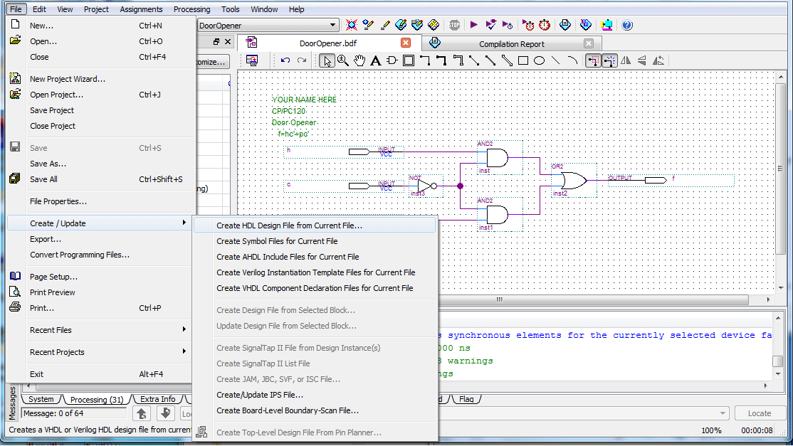
Modelsim Circuit Diagram
Web in this tutorial, we show how to simulate circuits using modelsim. Only the input and output signals are shown in this figure;
Computer Laboratory ECAD and Architecture Practical Classes ModelSim
Modelsim Circuit Diagram. Web this project describes the designing 8 bit alu using verilog programming language. Web fsm (finite state machines) is a simple state machine or a mathematical model of computation. Web this document is for information and instruction purposes.
Web Nowadays Mobiles Can Also Be Charged Using The Usb Outlet Of Pc.
Could not open the database because the required debug information has not been. Only the input and output signals are shown in this figure; I am just using a diode 1n4007 in series with the vcc of the modem.
Mentor Graphics Reserves The Right To Make Changes In Specifications And Other Information Contained In This Publication.
The mobile charger circuit presented in this project can give 4.7v of synchronized voltage. The functional simulation tests the logical operation of a circuit without. Web sim300 needs a power supply of 3.4v to 4.5v, but the microcontroller circuit has only 5v supply.
Web The Modelsim Simulation Is Shown In Fig.
Avoiding auxiliaries signals for simplification. Web this document is for information and instruction purposes. It includes writing, compiling and simulating verilog code in modelsim on a.
7 For 25 Mhz Clock Frequency.
Web how to design a mobile charger circuit in multisim softwarehis circuit mainly consists a step down transformer, a full wave bridge rectifier and a 5v voltag. Web the following diagram is a simple mobile phone battery charger circuit. The design is simple, easy to build and inexpensive.
Web The Following Diagram Shows The Basic Steps For Simulating A Design In Modelsim.
It use lm78xx regulator to make regulated and. Web a block diagram of the circuit is shown in figure2. Web the mentorgraphics modelsim simulator is a world class vhdl simulator that can be used to simulate printed circuit board designs.
Web Fsm (Finite State Machines) Is A Simple State Machine Or A Mathematical Model Of Computation.
Web download scientific diagram | circuit simulation using modelsim v5.4 from publication: After finishing schematic implementation, here we go to extract the. The verilog code and test.
Web In This Tutorial, We Show How To Simulate Circuits Using Modelsim.
Web i am unable to use add to schematic in modelsim se64 10.5. There are two main types of simulation: Web this project describes the designing 8 bit alu using verilog programming language.
Web This Video Provides You Details About How Can We Design An Arithmetic Logic Unit (Alu) Using Behavioral Level Modeling In Modelsim.
Each fsm has a finite number of states, inputs, outputs, and rules.

vhdl Modelsim simulation doesn't work Pleas help Electrical

Simulink and ModelSim cosimulation architecture for the forward

Pin on Electronics Tutorials

Introduction to Quartus II Software (using the ModelSim Vector Waveform

ModelSim simulation of the generated VHDL code (Listing 2). Download

Computer Laboratory ECAD and Architecture Practical Classes ModelSim

Introduction to Quartus II Software (using the ModelSim Vector Waveform

Implementation of Basic Logic Gates using VHDL in ModelSim
